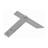
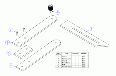
Here you can download free "do it yourself" project for making an engineer's sliding T bevel.
The sliding T bevel differs from the try square in having a movable blade. This blade may be set at any desired angle from 0 to 180 degrees. It consists of a stock with a slotted blade that can be set and locked at any angle. The sliding bevel is used for laying out angles other than 90 degrees and for testing constructed angles.

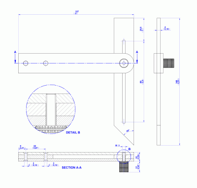
127mm (5'') x 89mm (3 1/2'') x 22mm (7/8'')
The same thing can be achieved with the sliding T-bevel or combination set, but the advantage is that this one is precisely made of metal and proves to be more suitable for small workpieces. In fact, it does not differ from the sliding T-bevel, except that it is of metal, and that it is found rather in metalworking than in woodworking workshops (where usually the sliding T-bevel is found). The engineer sliding T-bevel made according to our plan is cheaper when compared to the commercial one bought at the store, and it can be made in every workshop equipped with a milling machine or some other machine that can cut metal with precision and longitudinally.


To use the tool symply:
- set it to the required angle and then scribe lines at an angle on the workpiece
- check angle on the workpiece by the reverse procedure
On page Sliding T bevel you can see how to use both the engineer sliding T-bevel and the sliding T-bevel.